|
|
|
 Products > Discontinued Products > MYD-LPC435X (NXP LPC435x) > MYD-LPC435X Development Board
 |
| |
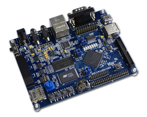 |
MYD-LPC435X Development Board |
- 204MHz NXP LPC4357, LPC4350 ARM Cortex-M4/M0 Dual-core Processors
- 32MB SDRAM, 2MB Nor Flash, 4MB SPI Data Flash
- UARTs, USB, Ethernet, CAN, RS485, TF, Audio, LCD, JTAG
- Complete MDK-ARM Sample Codes
- Optional 4.3" or 7.0" LCD/TSP
|
|
|
|
| |
|
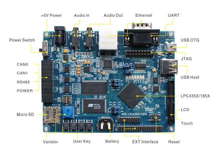
The MYD-LPC435X series development boards are designed based on NXP LPC4350 and LPC4357 ARM Cotex-M4 and Cortex-M0 asymmetrical dual-core processors which bring the advantage of developing DSP and MCU applications within a single architecture and development environment and can work at up to 204MHz. The MYD-LPC435X board takes full features of the two NXP ARM processors and has rich peripherals including 3 UARTs, USB Host, OTG, Ethernet, 2 CAN interfaces, RS485, LCD, Audio, etc. It has 32MB SDRAM, 2MB Nor Flash and 4MB Data Flash as well as one Micro SD card slot to enhance storage capabilities.
The MYD-LPC435X board may carry one of the two processors (NXP LPC4350 and LPC4357) as to make corresponding models:
MYD-LPC4350 Development Board (based on NXP LPC4350)
MYD-LPC4357 Development Board (based on NXP LPC4357)
The MYD-LPC435X board comes with plenty of Keil MDK-ARM source code and detailed document as well as some necessary cable accessories to help users evaluate, learning and make prototype based on NXP LPC4350 or LPC4357 ARM Cortex-M4 processor at a fast period. The board enables customers to develop a wide range of applications such as motor control, power management, industrial automation, robotics, medical, automotive accessories, and embedded audio.

MYD-LPC435X Development Board
Features
Processor
-
NXP LPC4350FET256 / LPC4357FET256
- 204 MHz, 32-bit ARM Cortex-M4 processor
- 204 MHz, 32-bit ARM Cortex-M0 asymmetrical coprocessor
- Up to 1 MB on-chip dual bank flash memory with flash accelerator (only for LPC4357)
- SRAM for code and data use (136 kB for LPC4357, 264 kB for LPC4350)
- 32 kB ROM containing boot code and on-chip software drivers
- 32 bit One-Time Programmable (OTP) memory for customer use
Memory and Storages
-
32MB SDRAM
-
2MB Nor Flash
-
4MB SPI Data FLASH
-
1 x Micro SD card slot
Audio Interface
-
Audio input
-
Stero audio output port
LCD/Touch screen
-
Support 24-bit true color, resolution up to 1024 x 768 pixels
-
4.3" LCD Module with resolution 480 x 272 pixels
-
7" LCD Module with resolution 800 x 480 pixels
-
4-wire resistive touch screen
Data interface
-
3 x UART (UART0, UART2 and UART3, UART2 need external MAX3232)
-
1 x Hi-speed USB HOST
-
1 x Mini USB OTG
-
1 x Ethernet interface
-
2 x CAN interface
-
1 x RS485 (reused with UART1)
-
20-pin JTAG interface
LED
-
1 x Power indicator
-
6 x User LED
Mechanical Parameters
-
Dimensions: 115mm x 90mm
-
PCB layers: 4-layer design
-
Power supply: 5V/2A or USB power supply
Sample Codes
-
Keil MDK-ARM example code
|
Hareware Specification
|
Product
|
MYD-LPC4350
|
MYD-LPC4357
|
|
Processor
|
|
MCU
|
NXP LPC4350
|
NXP LPC4357
|
|
Core
|
ARM Cortex-M4, Cortex-M0 coprocessor, working at 204MHZ
|
|
Internal SRAM
|
264KB
|
136KB
|
|
Internal ROM
|
32KB
|
32KB
|
|
Internal OTP
|
32bit
|
32bit
|
|
Internal FLASH
|
0
|
1MB
|
|
External memory and Storages
|
|
SDRAM
|
32MB
|
|
Nor Flash
|
2MB
|
|
SPI Data Flash
|
4MB
|
|
Micro SD card slot
|
1
|
|
Periphery interfaces
|
|
USB HOST
|
1
|
|
USB OTG
|
1
|
|
Ethernet
|
1
|
|
Serial port (UART0, 3)
|
2
|
|
RS485 (reused with UART1)
|
1
|
|
CAN
|
2
|
|
Interact Modules
|
|
LCD
|
1
|
|
Audio input
|
1
|
|
Audio oput
|
1
|
|
User button
|
4
|
|
System button
|
1
|
|
System interface
|
|
RTC
|
1
|
|
JTAG interface
|
1
|
|
User extend interface(Please refer to user manual for GPIO reuse setting)
|
|
Serial port(UART2)
|
1
|
|
ADC converter
|
8
|
|
DAC converter
|
1
|
|
SPI
|
1
|
|
I2C
|
2
|
|
GPIO Pins
|
20
|

|
Software Features
The MYD-LPC435X Development Board is provided with sample codes bundle for the peripherals using Keil's MDK-ARM to help users evaluate the NXP LPC4350 or LPC4357 ARM Cortex-M3 microcontroller.
|
Items
|
Name
|
Description
|
|
ADC
|
Adc_Burst
|
ADC converting under Burst Mode
|
|
Adc_Dma
|
ADC converting via DMA
|
|
Adc_Interrup
|
ADC converting under interrupt mode
|
|
Adc_Polling
|
ADC converting under polling mode
|
|
ATIMER
|
Atimer_Wic
|
Alarm Timer wake up system
|
|
BOOTFAST
|
Fast_Gpio_LedBlinky
|
Blinking LED by system working at 204MHZ
|
|
CCAN
|
CCan_SimpleTxRx
|
CAN communicationg (Connect CAN0 and CAN1)
|
|
Cortex-M4
|
CortexM4_Bitband
|
Cortex-M4 bit field test
|
|
CortexM4_Mpu
|
MPU test
|
|
CortexM4_Privilege
|
Switch privilege and non-privilege mode
|
|
DUALCORE
|
Int_Demo
|
Communication between M4 and M0
|
|
Mbx_Demo
|
Communication between M4 and M0
|
|
Queue_Demo
|
Communication between M4 and M0
|
|
EMAC
|
Emac_EasyWeb
|
Demonstrate WEB application running
|
|
EMC
|
Emc_NorFlash
|
External NorFlash read/write test
|
|
Emc_Sdram
|
External SDRAM read/write test
|
|
GPDMA
|
Gpdma_Flash2Ram
|
GDMA testing, from FLASH to RAM
|
|
Gpdma_LinkList
|
Use GPDMA Link-list
|
|
Gpdma_Ram2Ram
|
GPDMA,RAM to RAM
|
|
GPIO
|
Gpio_LedBlinky
|
GPIO driver LED blinking
|
|
I2C
|
I2c_Master
|
Read/Write UDA1380 via I2C
|
|
I2S
|
I2s_Audio
|
Output audio via I2S
|
|
LCD
|
Lcd_Demo
|
Display color streak, icon moved by touch
|
|
NVIC
|
Nvic_Priorities
|
Configure NVIC priority level test tail-chaining/Late-arriving interrupt mode
|
|
Nvic_VectorTableRelocation
|
Vector table relocation
|
|
OTP
|
OTP_API
|
OTP downloading test (development board can only boot from running code, SPIFI boot, please do it by carefully )
|
|
PWR
|
Pwr_DeepPowerDown
|
Fall into deep sleep mode and wake up from RTC
|
|
Pwr_DeepSleep
|
Fall into deep sleep mode and wake up from WIC
|
|
Pwr_PowerDown
|
Wake up by EVRT from power down mode
|
|
Pwr_Sleep
|
Wake up by WIC from sleep mode
|
|
RIT
|
Rit_Interrupt
|
Driver LED by RIT timer interrupt
|
|
RTC
|
Rtc_Alarm
|
Generate 1min and 30s Alarm interrupt
|
|
Rtc_Calibration
|
Calibration RTC
|
|
SDIO
|
sdio_readwrite
|
SDCard Read/Write test
|
|
SPIFI
|
SPIFI_Test
|
Read/Write external SPIFI Flash
|
|
SSP
|
Ssp_Master
|
SSP transfer data as host
|
|
Ssp_Slave
|
SSP transfer data as slave
|
|
TIMER
|
Timer_Capture
|
Timer capture
|
|
Timer_FreqMeasure
|
Timer measure frequency
|
|
Timer_MatchInterrupt
|
Timer interrupt test
|
|
Timer_MatchPolling
|
Timer match Polling
|
|
UART
|
Uart_Autobaud
|
UART auto-baud test
|
|
Uart_Dma
|
UART data via DMA test
|
|
Uart_Interrupt
|
UART interrupt
|
|
Uart_Polling
|
UART polling test
|
|
Uart_Rs485Master
|
RS485 host test
|
|
Uart_Rs485Slave
|
RS485 slave test
|
|
USBDEV
|
Usb_Cdc
|
USB simulate COM
|
|
Usb_MassStorage
|
Read/Write mass storage memory
|
|
USBDEV_ROM
|
Usb_Composite
|
Read/Write USB composite device(Mass Storage, HID,DFU)
|
|
Usb_Dfu
|
To be updated
|
|
Usb_Hid
|
Writing USB HID device
|
|
Usb_MassStorage
|
Writing USB Mass Storage
|
|
WDT
|
Wdt_Interrupt
|
Interrupt by WTD by setted time
|
|
Relative Download and Links
You can download relative chip datasheet, products datasheet, user manual, software package from below. Any inquiry, please contact MYIR.
|
1
|
MYD-LPC435X Development Board Overview
|
504 KB
|

|
|
2
|
MYD-LPC435x/185x Schematics
|
232 KB
|
|
|

MYD-LPC475X Development Board
|
Price and Ordering
Packing List
|
NO.
|
Item
|
Qty
|
Description
|
|
1
|
MYD-LPC435X board
|
1pc
|
MYD-LPC4350/MYD-LPC4357
|
|
2
|
Ethernet cable
|
1pc
|
|
|
3
|
USB Cable
|
1pc
|
|
|
4
|
Serial cable
|
1pc
|
DB9 to DB9
|
|
5
|
DVD
|
1pc
|
user manual, schematic in PDF format, datasheet, software package
|
|
More FAQ >>
1. Program can not downloadQuestion:Hello, I'm using your MYD-LPC435X board with ULINK2 for development. But now could not find "SPI-Flash LPC18xx@0x8000"drive, can not write spifi flash, can not download program, what's the problem?Answer:
About the LPC435X memory address, please refer to the user manual section 3.3 "MDK Configuration and Compilation".
Moreover, please erase the program of the internal flash before downloading program to SPI flash and confirm the SW2 position referring to section 2.4.2 "BOOT Setting".
When you use ULINK2 to download program, please pay attention to the Notes mentioned in section 3.4.2 "Download Program by ULINK2".
2. Add New CPU to DS-5 Device ListQuestion:How to add new CPU to DS-5 device list?Answer:
The document below introduces how to add new CPU to DS-5 device list? We use MYD-LPC4357 development board as the hardware platform for an example.
 Add New CPU to DS-5 Device List Add New CPU to DS-5 Device List
More FAQ >>
|
|
| |
|
|
|
|


 Overview
