|
|
|
 Products > Discontinued Products > MYD-LPC1788 (NXP LPC1788) > MYD-LPC1788 Development Board
 |
| |
 |
MYD-LPC1788 Development Board |
- 120MHz NXP LPC1788 ARM Cortex-M3 Microcontroller
- 32MB SDRAM, 1MB SRAM
- 2MB Nor Flash, 256KB EEPROM, 4MB SPI Data FLASH
- UARTs, USB, Ethernet, CAN, RS485, Audio, LCD, JTAG
- Provided with Complete MDK-ARM Sample Codes
- Optional 4.3" or 7.0" LCD/TSP
|
|
|
|
| |
|
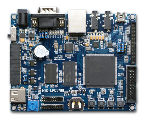
The MYD-LPC1788 development board is a full-featured evaluation platform based on NXP LPC1788 which is an ARM Cortex-M3 microcontroller for embedded applications featuring a high level of integration and low power consumption at frequencies of 120 MHz with 512 kB of flash memory, 96 kB of data memory, Ethernet, USB 2.0 Host/OTG/Device , 8-channel DMA controller, 5 UARTs, 2 CAN channels, 3 SSP/SPI, 3 I2C, I2S, 8-channel 12-bit ADC, 10-bit DAC, QEI, LCD controller, SD/MMC interface, motor control PWM, 4 general purpose timers, 6-output general purpose PWM, ultra-low power Real-Time Clock with separate battery supply, and up to 165 general purpose I/O pins.
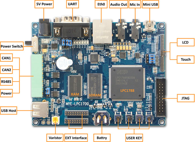
The MYD-LPC1788 development board takes full features of the NXP LPC1788 ARM Cortex-M3 microcontroller and exposes many peripherals including UARTs, USB, Ethernet, CAN, RS485, Audio, LCD and JTAG. The board has external 32MB SDRAM, 1MB SRAM, 2MB Nor Flash, 256KB EEPROM and 4MB SPI Flash to enhance the memory capabilities. The MYD-LPC1788 board is provided with plenty of MDK-ARM source code and detailed document as well as some necessary cable accessories to help users evaluate, learning and make prototype based on NXP LPC1788 ARM Cortex-M3 processor at a fast period.
The MYD-LPC1788 Development board can be used in various applications such as Metering, Lighting, Industrial networking, Alarm systems, White goods and Motor control.

MYD-LPC1788 Development Board
Features
Processor
-
NXP LPC1788FBD208, ARM Cortex-M3 Microcontroller, working at 120MHz
- 96 KB SRAM for code and data use
- 512 KB ROM containing boot code and on-chip software drivers
- 4 KB EEPROM
External Memory
-
32 MB SDRAM
-
1 MB SRAM
-
2 MB Nor Flash
-
256 KB EEPROM
-
4 MB SPI Data FLASH
Audio Interface
-
Audio input
-
Stero audio output port
LCD/Touch screen
-
Support 24-bit true color, resolution up to 1024 x 768 pixels
-
4.3" LCD Module with resolution 480 x 272 pixels
-
7" LCD Module with resolution 800 x 480 pixels
-
4-wire resistive touch screen
Data interface
-
1 x Serial port (select UART0 or UART2 by jumper)
-
1 x RS485 interface
-
1x Hi-speed USB HOST
-
1 x Mini USB OTG
-
1 x Ethernet interface
-
2 x CAN interfaces
-
20-pin JTAG interface
LED
Mechanical Parameters
-
PCB Size: 115mm x 90mm
-
PCB layers: 4-layer design
-
Power supply: 5V/2A or USB Power supply
-
Debug interface: 20-pin, 2.54mm JTAG connector
Sample Codes
-
Sample codes for peripherals using Keil's MDK-ARM
|
The LPC1788 is a Cortex-M3 microcontroller for embedded applications featuring a high level of integration and low power consumption at frequencies of 120 MHz. Features include 512 kB of flash memory, 96 kB of data memory, Ethernet, USB 2.0 Host/OTG/Device , 8-channel DMA controller, 5 UARTs, 2 CAN channels, 3 SSP/SPI, 3 I2C, I2S, 8-channel 12-bit ADC, 10-bit DAC, QEI, LCD controller, SD/MMC interface, motor control PWM, 4 general purpose timers, 6-output general purpose PWM, ultra-low power Real-Time Clock with separate battery supply, and up to 165 general purpose I/O pins.
The MYD-LPC1788 takes full features of the microcontroller and exposes many of these features to the user in support of developing specific solutions. This board is characterized as follows:
Processor
-
NXP LPC1788, ARM Cortex-M3 Microcontroller, working at 120MHz
- 96 KB SRAM for code and data use
- 512 KB ROM containing boot code and on-chip software drivers
- 4 KB EEPROM
External Memory
-
32 MB SDRAM
-
1 MB SRAM
-
2 MB Nor Flash
-
256 KB EEPROM
-
4 MB SPI Data FLASH
Audio Interface
-
Audio input
-
Stereo audio output port
LCD/Touch screen
-
Support 24-bit true color, resolution up to 1024 x 768 pixels
-
4.3" LCD Module with resolution 480 x 272 pixels
-
7" LCD Module with resolution 800 x 480 pixels
-
4-wire resistive touch screen
Data interface
-
1 x Serial port (select UART0 or UART2 by jumper)
-
1 x RS485 interface
-
1x Hi-speed USB HOST
-
1 x Mini USB OTG
-
1 x Ethernet interface
-
2 x CAN interfaces
-
20-pin JTAG interface
LED
Mechanical Parameters
-
PCB Size: 115mm x 90mm
-
PCB layers: 4-layer design
-
Power supply: 5V/2A or USB Power supply
-
Debug interface: 20-pin, 2.54mm JTAG connector
|
Software Features
The MYD-LPC1788 Development Board is provided with sample codes bundle for the peripherals using Keil's MDK-ARM to help users evaluate the NXP LPC1788 ARM Cortex-M3 microcontroller.
|
No
|
Name
|
Description
|
|
1
|
ADC_Interrupt
|
ADC converting under Burst Mode
|
|
2
|
ADC_Polling
|
ADC converting under polling mode
|
|
3
|
CAN_Test
|
CAN Test
|
|
4
|
Crc_Demo
|
CRC Test
|
|
5
|
Dac_Dma
|
DMA data to DAC convert
|
|
6
|
Dac_SineWave
|
DMA data to DAC generating sin
|
|
7
|
DMA_Flash2Ram
|
GPDMA test, data from FLASH to RAM
|
|
8
|
Eeprom_Demo
|
Write data onLPC1788’s EEPROM
|
|
9
|
Emc_NorFlashDemo
|
Read/write to NorFlash by EMC
|
|
10
|
Emc_SdramDemo
|
Read/write SDRAM by EMC interface
|
|
11
|
Emc_SramDemo
|
Read/write SRAM by EMC interface
|
|
12
|
GPIO_Interrupt
|
GPIO test
|
|
13
|
GPIO_LedBlinky
|
Led blinking
|
|
14
|
Nvic_VectorTableRelocation
|
Vector table relocation
|
|
15
|
Pwm_SingleEdge
|
6 channels generate PWM signal under single edge mode
|
|
16
|
Pwm_DualEdge
|
3 channels generate PWM signal under dual edge mode
|
|
17
|
Pwm_MatchInerrupt
|
PWM match under interrupt mode
|
|
18
|
PWR_Sleep
|
Fall into deep sleep mode and wake up by WWDT
|
|
19
|
PWR_DeepSleep
|
Fall into deep sleep mode and wake up
|
|
20
|
Emac_EasyWeb
|
A Web application running on LPC1788
|
|
21
|
Rtc_Alarm
|
RTC Test
|
|
22
|
SSP_Touchscreen
|
SSP interface read touch panel data
|
|
23
|
SSP_Flash
|
Read/write AT25DV321A by SSP interface
|
|
24
|
Systick_100msBase
|
System tick, interrupt by each 100ms
|
|
25
|
Timer_MatchInterrupt
|
Set time interval by time capture
|
|
26
|
Wdt_Interrupt
|
WDT trigger overtime and warning interrupt
|
|
27
|
Wdt_Reset
|
Reset event happen by WDT after setted time
|
|
28
|
Lcd_LQ043T3DX0A
|
Display a picture
|
|
29
|
Lcd_touch
|
Touch screen test
|
|
30
|
Mci_CidCard
|
Read SD card by MCI interface
|
|
31
|
Usb_MassStorage
|
USB Mass storage application
|
|
32
|
Usb_VirtualCom
|
Configure USB device as a stimulate COM port
|
|
33
|
I2C_Eeprom
|
Read/Write EEPROM via I2C
|
|
34
|
RS_485-Master & Slave
|
RS_485 communication between Master & Slave
|
|
Relative Download and Links
You can download relative chip datasheet, products datasheet, user manual, software package from below. Any inquiry, please contact MYIR.
|
1
|
MYD-LPC1788 Overview
|
252 KB
|

|
|
2
|
MYD-LPC1788 Schematics
|
225 KB
|

|
|

MYD-LPC1788 Development Board
|
Price and Ordering
Packing List
|
NO.
|
Item
|
Qty
|
Description
|
|
1
|
MYD-LPC1788 board
|
1pc
|
MYD-LPC1788 development board
|
|
2
|
Ethernet cable
|
1pc
|
|
|
3
|
USB Cable
|
1pc
|
|
|
4
|
Serial cable
|
1pc
|
DB9 to DB9
|
|
5
|
DVD
|
1pc
|
user manual, schematic in PDF format, datasheet, software package
|
|
|
| |
|
|
|
|