1. Overview
The NXP i.MX93 processor features two Ethernet controllers, one of which is the EQOS TSN (Time-Sensitive Networking) network controller. The other is the FEC (Fast Ethernet Controller) peripheral device that enables the device to transmit and receive data conforming to the IEEE 802.3-2002 standard over Ethernet, providing a configurable and flexible peripheral to meet the needs of various applications and customers.
Typically, the CPU integrates the MAC, and the PHY uses a separate chip; when the CPU does not integrate the MAC, both the MAC and PHY are integrated into a single chip. The MAC and PHY operate at the data link layer and physical layer of the OSI model. Since the MAC of i.MX93 is integrated within the CPU, an external PHY chip is required.
The MYD-LMX9X development board is based on NXP's i.MX 9352 processor. It is connected to two YT8531SH Gigabit PHY chips, and the schematic diagram of ENET1 is shown in Figure 1-1:
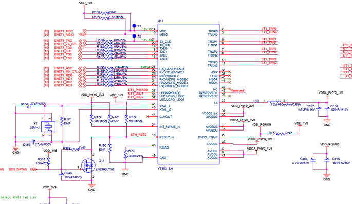
Figure 1-1 ENET1 diagram
Review the schematic and the document "MYD-LMX9X-PinList-V1.0.pdf" to determine the corresponding relationship between the ENET1 data pins and the i.MX93 as shown in Table 1-2.
|
Pin Function
|
Pin No.
|
|
ENET1_MDC
|
B31
|
|
ENET1_MDIO
|
B32
|
|
ENET1_TXC
|
B22
|
|
ENET1_TX_CTL
|
B23
|
|
ENET1_TD0
|
B3
|
|
ENET1_TD1
|
B21
|
|
ENET1_TD2
|
B2
|
|
ENET1_TD3
|
B1
|
|
ENET1_RXC
|
B30
|
|
ENET1_RX_CTL
|
B29
|
|
ENET1_RD0
|
B28
|
|
ENET1_RD1
|
B27
|
|
ENET1_RD2
|
B26
|
|
ENET1_RD3
|
B25
|
Table 1-2 ENET1 Pinlist
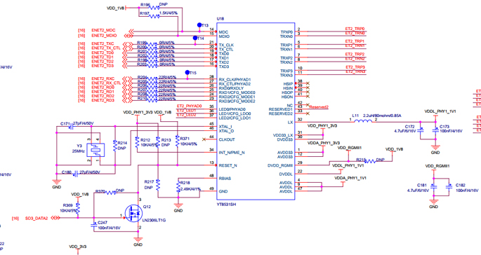
Figure 1-1 ENET2 diagram
Review the schematic and the document "MYD-LMX9X-PinList-V1.0.pdf" to determine the corresponding relationship between the ENET2 data pins and the MYD-LMX9X as shown in Table 1-4.
|
Pin Function
|
Pin No.
|
|
ENET2_MDC
|
B5
|
|
ENET2_MDIO
|
B6
|
|
ENET2_TXC
|
B19
|
|
ENET2_TX_CTL
|
B14
|
|
ENET2_TD0
|
B17
|
|
ENET2_TD1
|
B16
|
|
ENET2_TD2
|
B15
|
|
ENET2_TD3
|
B18
|
|
ENET2_RXC
|
B12
|
|
ENET2_RX_CTL
|
B10
|
|
ENET2_RD0
|
B11
|
|
ENET2_RD1
|
B8
|
|
ENET2_RD2
|
B9
|
|
ENET2_RD3
|
B7
|
Table 1-4 ENET2 Pinlist
2. Ethernet driver porting
2-1. View the pin definitions of kernel device
In the kernel, there is a definition for the Ethernet device tree resources of the i.MX93 chip, which is provided by the chip manufacturer. In fact, we do not need to modify this part, just reference it as follows:
PC:~/myd-lmx9x-bsp/myir-imx-linux$ cat arch/arm64/boot/dts/myir/imx93.dtsi
......
fec: ethernet@42890000 {
compatible = "fsl,imx93-fec", "fsl,imx8mp-fec", "fsl,imx8mq-fec";
reg =;
interrupts =,
,
,
;
clocks = <&clk IMX93_CLK_ENET1_GATE>,
<&clk IMX93_CLK_ENET1_GATE>,
<&clk IMX93_CLK_ENET_TIMER1>,
<&clk IMX93_CLK_ENET_REF>,
<&clk IMX93_CLK_ENET_REF_PHY>;
clock-names = "ipg", "ahb", "ptp",
"enet_clk_ref", "enet_out";
assigned-clocks = <&clk IMX93_CLK_ENET_TIMER1>,
<&clk IMX93_CLK_ENET_REF>,
<&clk IMX93_CLK_ENET_REF_PHY>;
assigned-clock-parents = <&clk IMX93_CLK_SYS_PLL_PFD1_DIV2>,
<&clk IMX93_CLK_SYS_PLL_PFD0_DIV2>,
<&clk IMX93_CLK_SYS_PLL_PFD1_DIV2>;
assigned-clock-rates =,,;
fsl,num-tx-queues =;
fsl,num-rx-queues =;
fsl,stop-mode = <&wakeupmix_gpr 0x0c 1>;
status = "disabled";
};
eqos: ethernet@428a0000 {
compatible = "nxp,imx93-dwmac-eqos", "snps,dwmac-5.10a";
reg =;
interrupts =,
;
interrupt-names = "eth_wake_irq", "macirq";
clocks = <&clk IMX93_CLK_ENET_QOS_GATE>,
<&clk IMX93_CLK_ENET_QOS_GATE>,
<&clk IMX93_CLK_ENET_TIMER2>,
<&clk IMX93_CLK_ENET>,
<&clk IMX93_CLK_ENET_QOS_GATE>;
clock-names = "stmmaceth", "pclk", "ptp_ref", "tx", "mem";
assigned-clocks = <&clk IMX93_CLK_ENET_TIMER2>,
<&clk IMX93_CLK_ENET>;
assigned-clock-parents = <&clk IMX93_CLK_SYS_PLL_PFD1_DIV2>,
<&clk IMX93_CLK_SYS_PLL_PFD0_DIV2>;
assigned-clock-rates =,;
intf_mode = <&wakeupmix_gpr 0x28>;
clk_csr =;
nvmem-cells = <ð_mac2>;
nvmem-cell-names = "mac-address";
status = "disabled";
The above mentioned process only performs basic initialization on the Ethernet port, without adapting it to specific hardware devices. In practice, it is necessary to adapt the hardware pin resources for the specific Ethernet port.
2-2. Add Ethernet device tree node
Add device tree configuration for Ethernet port based on the definition of the schematic diagram, modify the myir-imx93-11x11.dts file as follows:
PC:~/myd-lmx9x-bsp/myir-imx-linux$ cat arch/arm64/boot/dts/myir/myir-imx93-11x11.dts
......
&eqos {
pinctrl-names = "default";
pinctrl-0 = <&pinctrl_eqos>;
phy-mode = "rgmii-id";
phy-handle = <ðphy1>;
status = "okay";
mdio {
compatible = "snps,dwmac-mdio";
#address-cells =;
#size-cells =;
clock-frequency =;
ethphy1: ethernet-phy@1 {
compatible = "ethernet-phy-ieee802.3-c22";
reg =;
eee-broken-1000t;
};
};
};
&fec {
pinctrl-names = "default";
pinctrl-0 = <&pinctrl_fec>;
phy-mode = "rgmii-id";
phy-handle = <ðphy2>;
fsl,magic-packet;
status = "okay";
mdio {
compatible = "snps,dwmac-mdio";
#address-cells =;
#size-cells =;
clock-frequency =;
ethphy2: ethernet-phy@2 {
compatible = "ethernet-phy-ieee802.3-c22";
reg =;
eee-broken-1000t;
};
};
};
2-3. Ethernet device tree configuration
Add the pin definitions for eth1_pins and eth2_pins to the Ethernet device tree node.
pinctrl_eqos: eqosgrp {
fsl,pins = <
MX93_PAD_ENET1_MDC__ENET_QOS_MDC 0x57e
MX93_PAD_ENET1_MDIO__ENET_QOS_MDIO 0x57e
MX93_PAD_ENET1_RD0__ENET_QOS_RGMII_RD0 0x57e
MX93_PAD_ENET1_RD1__ENET_QOS_RGMII_RD1 0x57e
MX93_PAD_ENET1_RD2__ENET_QOS_RGMII_RD2 0x57e
MX93_PAD_ENET1_RD3__ENET_QOS_RGMII_RD3 0x57e
MX93_PAD_ENET1_RXC__CCM_ENET_QOS_CLOCK_GENERATE_RX_CLK 0x5fe
MX93_PAD_ENET1_RX_CTL__ENET_QOS_RGMII_RX_CTL 0x57e
MX93_PAD_ENET1_TD0__ENET_QOS_RGMII_TD0 0x57e
MX93_PAD_ENET1_TD1__ENET_QOS_RGMII_TD1 0x57e
MX93_PAD_ENET1_TD2__ENET_QOS_RGMII_TD2 0x57e
MX93_PAD_ENET1_TD3__ENET_QOS_RGMII_TD3 0x57e
MX93_PAD_ENET1_TXC__CCM_ENET_QOS_CLOCK_GENERATE_TX_CLK 0x5fe
MX93_PAD_ENET1_TX_CTL__ENET_QOS_RGMII_TX_CTL 0x57e
>;
};
pinctrl_fec: fecgrp {
fsl,pins = <
MX93_PAD_ENET2_MDC__ENET1_MDC 0x57e
MX93_PAD_ENET2_MDIO__ENET1_MDIO 0x57e
MX93_PAD_ENET2_RD0__ENET1_RGMII_RD0 0x57e
MX93_PAD_ENET2_RD1__ENET1_RGMII_RD1 0x57e
MX93_PAD_ENET2_RD2__ENET1_RGMII_RD2 0x57e
MX93_PAD_ENET2_RD3__ENET1_RGMII_RD3 0x57e
MX93_PAD_ENET2_RXC__ENET1_RGMII_RXC 0x5fe
MX93_PAD_ENET2_RX_CTL__ENET1_RGMII_RX_CTL 0x57e
MX93_PAD_ENET2_TD0__ENET1_RGMII_TD0 0x57e
MX93_PAD_ENET2_TD1__ENET1_RGMII_TD1 0x57e
MX93_PAD_ENET2_TD2__ENET1_RGMII_TD2 0x57e
MX93_PAD_ENET2_TD3__ENET1_RGMII_TD3 0x57e
MX93_PAD_ENET2_TXC__ENET1_RGMII_TXC 0x5fe
MX93_PAD_ENET2_TX_CTL__ENET1_RGMII_TX_CTL 0x57e
>;
};
2-4. Configure kernel
The PHY driver is located at drivers/net/phy/motorcomm. c. We just need to enable this driver and compile it into the kernel. The kernel already has the Ethernet driver configured by default, so we will not describe it here. Finally, compile the kernel source code and update the newly generated device tree dtb file to the board.
2-5. Ethernet testing
Test ENET1
root@myd-lmx9x:/# ping www.baidu.com -I eth0
PING www.baidu.com (14.215.177.39): 56 data bytes
64 bytes from 14.215.177.39: seq=0 ttl=56 time=7.987 ms
64 bytes from 14.215.177.39: seq=1 ttl=56 time=8.030 ms
64 bytes from 14.215.177.39: seq=2 ttl=56 time=7.250 ms
Test ENET2
root@myd-lmx9x:/# ping www.baidu.com -I eth1
PING www.baidu.com (14.215.177.39): 56 data bytes
64 bytes from 14.215.177.39: seq=3 ttl=56 time=7.507 ms
64 bytes from 14.215.177.39: seq=4 ttl=56 time=7.488 ms
64 bytes from 14.215.177.39: seq=5 ttl=56 time=7.151 ms
64 bytes from 14.215.177.39: seq=6 ttl=56 time=7.043 ms
MYC-LMX9X System-On-Module and MYD-LMX9X Development Board
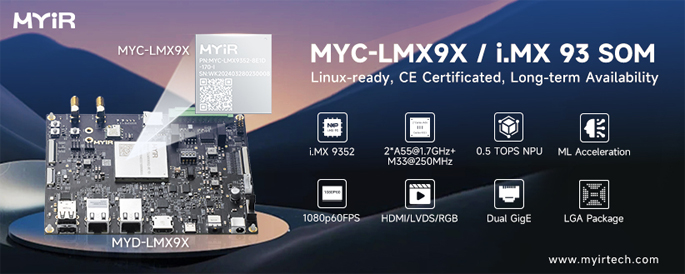
- Tiny SOM measuring just 37mm x 39mm, with a 218-pin LGA expansion interface for easy integration and customization
- NXP i.MX 9352 Application Processor based on 1.7 GHz Dual Arm Cortex-A55 and 250MHz Cortex-M33 Cores
- Integrated 0.5 TOPS Neural Processing Unit (NPU), enabling cost-effective and lightweight AI applications
- 1GB/2GB LPDDR4, 8GB eMMC Flash, 32KB EEPROM
- 2x USB 2.0 Host, 1x USB 2.0 OTG, 1x Micro SD Card Slot, CAN/RS485/RS232
- 2x Gigabit Ethernet, 1x 4G/5G Module Interface, 1x WiFi Module
- Supports HDMI and LVDS Display, Camera Interface (MIPI-CSI), Audio Input and Output
- Supports Working Temperature Ranging from -40°C to 85°C
- Supports for Linux 6.1 and Debian 12
MYIR also offers ODM and OEM services. MYIR's SMT smart factory offers one-stop PCBA manufacturing services.

Visit MYIR's Smart Factory Online
********************************************************************************************************************************************************
Latest Star SOMs from MYIR
|