Here we introduce an e-Paper Display demo working on
MYIR’s MYD-YA15XC-T development board through SPI interface. The
MYD-YA15XC-T board is based on ST STM32MP151 MPU which is a heterogeneous multi-core
processor. The following will mainly introduce how to drive the e-Paper display
through SPI interface in Cortex-M4 and A7 cores of STM32MP151 respectively.
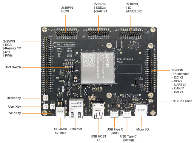
MYD-YA15XC-T Development Board Top-view
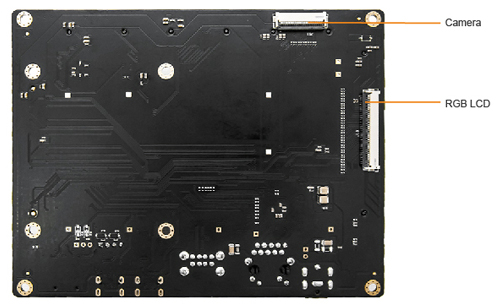
MYD-YA15XC-T Development Board Bottom-view
1. Hardware resources
- One MYD-YA15XC-T
Development Board and accessories
- Two USB-TTL
Debug cables
- One Waveshare 2.7-inch e-Paper HAT, for Raspberry Pi, 2.7inch, 264x176 resolution, with embedded controller,
communicating via SPI interface.
2. Software resources
- Linux 5.4.31
- STM32CubeIDE
1.5.0
- Linux
virtual machine
- SDK provided
by MYIR
3. Development Environment Preparation
Pre-install
CubeIDE and other development software, then set up Linux virtual machine
environment. For detailed environment setup steps, please refer to “MYD-YA15XC-T_Software
Development Guide”.
4. Operating Steps
4.1 Drive the e-Paper display via SPI interface from
Cortex-A7 core
The Display vendors will
provide driver demos generally. The user needs to know about the control chip
of the display, the effective signal levels and character transmission mode of Chip
Select so as to save time when porting the vendor’s demo.
The e-Paper display can be
used as a slave device under the SPI bus. The user only needs to write their
applications, then transplant the initialization code and the image processing
code of the display provided by vendors, it will display.
Please refer to Wareshare
website for the display refresh principle:
https://www.waveshare.com/wiki/2.7inch_e-Paper_HAT
1) Configuring the Device Tree
Enter the kernel
source directory stm32mp15xc-kernel5.4/arch/arm/boot/dts and use vim to open the
stm32mp15xx-ya157c.dtsi device tree file, configure the SPI device as follows:
vi
stm32mp15xx-ya157c.dtsi
&spi5 {
pinctrl-names = "default",
"sleep";
pinctrl-0 = <&spi5_pins_mx>;
pinctrl-1 =
<&spi5_sleep_pins_mx>;
cs-gpios = <&gpioi 11 0>;
spidev@0 {
compatible = "spidev";
spi-max-frequency =;
reg =;
};
};
After compiling and
updating the device tree, restart the development board and you can see that
the system generates the /dev/spidev0.0 device node, which will be needed by application
programs later.
2) Programming application
This step needs to
transplant the screen initialization program to the ST platform (Waveshare has provided
PNG image processing function to help users to do image processing more
conveniently).
First user needs to open
the device node to get the device descriptor and set the SPI parameters:
void DEV_HARDWARE_SPI_begin(char *SPI_device)
{
//device
printf("test hardware\n");
int ret = 0;
if((hardware_SPI.fd = open(SPI_device,
O_RDWR )) < 0) {
perror("Failed to open SPI
device.\n");
DEV_HARDWARE_SPI_Debug("Failed
to open SPI device\r\n");
exit(1);
} else {
printf("open:%s\r\n",SPI_device);
DEV_HARDWARE_SPI_Debug("open :
%s\r\n", SPI_device);
}
hardware_SPI.mode = 0;
ret = ioctl(hardware_SPI.fd,
SPI_IOC_WR_BITS_PER_WORD, &bits);
if (ret == -1) {
DEV_HARDWARE_SPI_Debug("can't
set bits per word\r\n");
}
ret = ioctl(hardware_SPI.fd,
SPI_IOC_RD_BITS_PER_WORD, &bits);
if (ret == -1) {
DEV_HARDWARE_SPI_Debug("can't get
bits per word\r\n");
}
tr.bits_per_word = bits;
DEV_HARDWARE_SPI_Mode(SPI_MODE_0);
DEV_HARDWARE_SPI_ChipSelect(SPI_CS_Mode_LOW);
DEV_HARDWARE_SPI_SetBitOrder(SPI_BIT_ORDER_MSBFIRST);
DEV_HARDWARE_SPI_setSpeed(20000000);
DEV_HARDWARE_SPI_SetDataInterval(0);
}
3) Testing
Copy the
application epaper and display images to the development board directory:
-rwxr-xr-x
1 root root 137520 Apr 29 2021 epaper
Change the permissions and
execute the program:
root@myir-ya157c-t:~#
chmod a+x epaper
root@myir-ya157c-t:~#
./epaper
EPD_2IN7_test
Demo
/***********************************/
Current
environment: ST
Write
and read /dev/spidev0.0
Debug:
Export: Pin136
Debug:
Pin136:Output
Debug:
OUT Pin = 136
Debug:
Export: Pin117
Debug:
Pin117:Output
Debug:
OUT Pin = 117
Debug:
Export: Pin35
Debug:
Pin35:Output
Debug:
OUT Pin = 35
Debug:
Export: Pin29
Debug:
Pin29:intput
Debug:
IN Pin = 29
test
hardware
open:/dev/spidev0.0
/***********************************/
e-Paper
Init and Clear...
Debug:
Data= spi test
Debug:
e-Paper busy
Debug:
e-Paper busy release
Debug:
init success
Debug:
e-Paper busy
Debug:
e-Paper busy release
Paint_NewImage
show
window BMP-----------------
pixel
= 100 * 100
Debug:
e-Paper busy
Debug:
e-Paper busy release
show
bmp------------------------
pixel
= 264 * 176
Debug:
e-Paper busy
Debug:
e-Paper busy release
show
image for array
Debug:
e-Paper busy
Debug:
e-Paper busy release
SelectImage:BlackImage
Drawing:BlackImage
EPD_Display
Debug:
e-Paper busy
Debug:
e-Paper busy release
Clear...
show
Gray------------------------
4
grayscale display
Debug:
e-Paper busy
Debug:
e-Paper busy release
Debug:
e-Paper busy
Debug:
e-Paper busy release
Debug:
e-Paper busy
Debug:
e-Paper busy release
pixel
= 176 * 264
biBitCount
= 4
bmpInfoHeader.biWidth
= 176
bmpInfoHeader.biHeight
= 264
Debug:
e-Paper busy
Debug:
e-Paper busy release
pixel
= 100 * 100
Debug:
e-Paper busy
Debug:
e-Paper busy release
Debug:
e-Paper busy
Debug:
e-Paper busy release
Goto
Sleep...
close
5V, Module enters 0 power consumption ...
root@myir-ya157c-t:~#
ls
After the execution of the program,
you can see the pictures are displayed in turn correspondingly.
4.2 Drive the e-Paper
display via SPI interface from Cortex-M4 core
1) Allocate SPI5 to Cortex-M4 core
The M4 core needs to use
SPI5, so the users need to assign SPI5 peripherals to the M4 core in the kernel
device tree, and the pins are self-configured according to the circuit diagram as
shown below:
/*SPI5 for M4 core*/
&m4_spi5 {
pinctrl-names = "rproc_default";
pinctrl-0 =
<&m4_spi5_pins_mx>;
status = "okay";
};
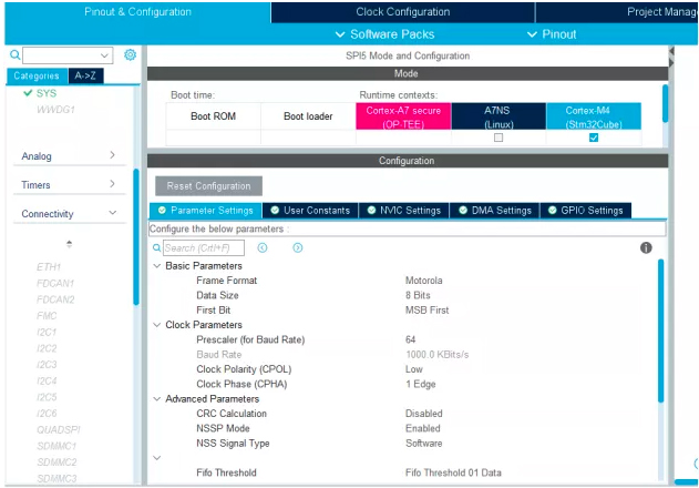
2) CubeMX configuration
Create an STM32 project,
configure SPI to control the e-paper screen and serial port to output Debug
messages in STM32CubeMX in order.
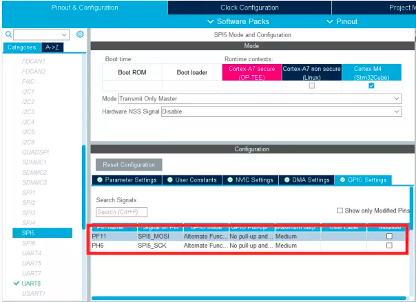
Figure
4-1 Configuring SPI pins
Figure 4-2 Configuring SPI Parameters
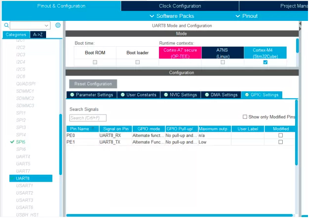
Figure
4-3 Configuring the Debug serial port
3) Generating code
Since the hardware SPI is
used, there is no need to implement SPI protocol timing then. After the
generation of code, create a new directory "User" under CM4 directory
in M4 project in order to save your own codes, and then copy the initialization
program of the e-Paper display to the directory:
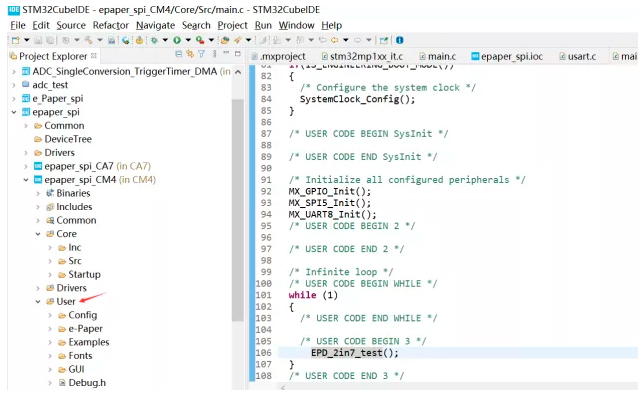
Figure 4-4 Adding custom file
directory
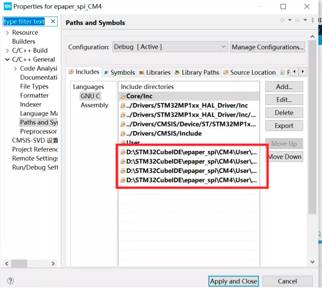
Right-click Properties, set
M4 project properties, and add the custom header file path:
Figure
4-5 Adding custom header file path
In the main program user only
needs to call the SPI screen test program, as follows:
int
main(void)
{
/* USER CODE BEGIN 1 */
/* USER CODE END 1 */
/* MCU
Configuration--------------------------------------------------------*/
/* Reset of all peripherals, Initializes the
Flash interface and the Systick. */
HAL_Init();
/* USER CODE BEGIN Init */
/* USER CODE END Init */
if(IS_ENGINEERING_BOOT_MODE())
{
/* Configure the system clock */
SystemClock_Config();
}
/* USER CODE BEGIN SysInit */
/* USER CODE END SysInit */
/* Initialize all configured peripherals */
MX_GPIO_Init();
MX_SPI5_Init();
MX_UART8_Init();
/* USER CODE BEGIN 2 */
/* USER CODE END 2 */
/* Infinite loop */
/* USER CODE BEGIN WHILE */
while (1)
{
/* USER CODE END WHILE */
/* USER CODE BEGIN 3 */
EPD_2in7_test();
}
/* USER CODE END 3 */
}
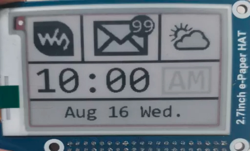
4) Testing
Compile and generate M4
firmware (such as epaper_spi_CM4.elf), copy it to development board and run,
then you can see the screen can display pictures in a loop:
root@myir-ya157c-t:~#
cp epaper_spi_CM4.elf /lib/firmware/
root@myir-ya157c-t:~#
echo epaper_spi_CM4.elf > /sys/class/remoteproc/remoteproc
0/firmware
root@myir-ya157c-t:~#
echo start > /sys/class/remoteproc/remoteproc0/state
[21811.808271]
remoteproc remoteproc0: powering up m4
[21811.817832]
remoteproc remoteproc0: Booting fw image epaper_spi_CM4.elf, size 2687232
[21811.824427]
remoteproc remoteproc0: header-less resource table
[21811.830087]
remoteproc remoteproc0: no resource table found for this firmware
[21811.837556]
remoteproc remoteproc0: header-less resource table
[21811.848595]
rproc-srm-core mlahb:m4@10000000:m4_system_resources: bound
mlahb:m4@10000000:m4_system_resources:timer@44000000 (ops 0xc0e07aac)
[21811.862747]
remoteproc remoteproc0: remote processor m4 is now up
5) Display effect
Know more about
MYIR’s MYD-YA15XC-T
development board from:
http://www.myirtech.com/list.asp?id=659
The MYD-YA15XC-T
development board is
using the MYC-YA15XC-T
CPU Module as core
controller board which is populated on a specially designed base board
through 1.0
mm pitch 148-pin stamp-hole (Castellated-Hole) expansion interface.
It is capable of running Linux OS. MYIR also offers MY-CAM011B
Camera Module, MY-RGB2HDMI Module, MY-WF005S WiFi/BT Module, MY-WIREDCOM RPI Module (RS232/RS485/CAN) and MY-LCD70TP-C LCD
Module as
options for the board.
MYIR provides custom design services based on the
MYD-YA15XC-T, whether reducing, adding or modifying the existing hardware
according to customer’s requirement.
|