MYIR has launched a high-performance development board MYD-YA15XC-T recently
which is a good reference design for using ST
STM32MP1 processors which features 650MHz Single or Dual Arm Cortex-A7 and 209MHz Cortex-M4 Cores.

Below gives an example
on how to debug LoRa with Cortext-M4 ARM core, based on MYIR’s MYD-YA15XC-T development board and a Raspberry LoRa expansion board.
1. Hardware
- One MYD-YA15XC-T
Development Board
- One Type-C Debug cable
- One Micro USB cable
- Two SX1262 868M LoRa HAT modules for Raspberry Pi
2. Software
- Linux 5.4.31
- STM32CubeIDE 1.5.0
- Linux virtual machine
- SDK provided by MYIR
3. Development Environment
Pre-install CubeIDE and
other development software, and set up Linux virtual machine environment. For
detailed environment setup steps, please refer to “MYD-YA15XC-T_Software
Development Guide”.
4. Operating Steps
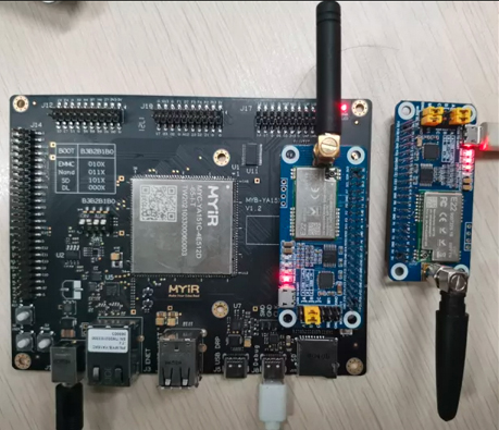
4.1. Wiring and setting
Connect
one LoRa module with the PC through the Micro USB cable; put its jumper cap on
A; M1 and M0 are connected to GND. Open the SSCOM serial port software and
connect to the LoRa module. Put the jumper cap of the other
LoRa module on B; remove the jumper cap for M0 and M1 and use them as GPIOs
for the MYD-YA15XC-T development board as shown in the figure below:
4.2 CubeMX Configuration
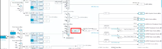
1. Set the clock to 209M. As shown below, just type 209M in the red box
and press "Enter". The clock parameters will be set automatically:
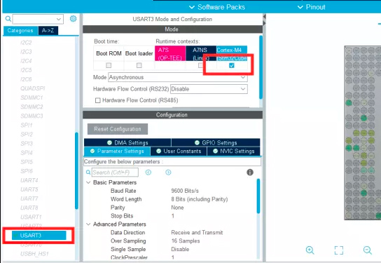
2. Since the communication interface of this module
uses a serial port, it is also necessary to set the USART peripheral and enable
interrupt:
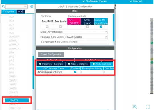
3. Then select serial interrupt to send and
receive through interrupt:
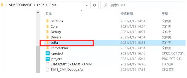
4.3 Software design
After generating the code from section 4.2,
create a new "LoRa" directory in the project to store the LoRa
configuration code (Source code can be obtained from Waveshare website, users can port it directly):
1. To set the register configuration mode, we
first need to set mode 2 here for register configuration:
void
cfg_sx126x_io(uint8_t status)
{
if(CFG_REGISTER == status){
M0_RESET();
M1_SET();
HAL_Delay(5);
}else if(NORMAL_STATUS == status){
M0_RESET();
M1_RESET();
HAL_Delay(5);
}else if(WOR_STATUS == status){
M0_SET();
M1_RESET();
HAL_Delay(5);
}else if(SLEEP_STATUS == status){
M0_SET();
M1_SET();
HAL_Delay(5);
}
}
2. Configure the register, set baud rate
9600 and broadcast monitor address:
/******************************************************************************
sx126x mode : broadcast & monitor mode
parameter:
address_high: 0xff
address_low: 0xff
net_id:
0x00
serial: 0x62
power: 0x00
channel: 0x12
transmission_mode:
0x03
crypt_high: 0x00
crypt_low: 0x00
******************************************************************************/
lora_para_t
transparent_mode = {
.address_high = BROADCAST_ADDH_VALUE,
.address_low = BROADCAST_ADDL_VALUE,
.net_id = BROADCAST_NETID_VALUE,
.serial = BROADCAST_SERIAL_VALUE,
.power = BROADCAST_POWER_VALUE,
.channel = BROADCAST_CHANNEL_VALUE,
.transmission_mode = BROADCAST_TRANSIMISSION_VALUE,
.crypt_high = BROADCAST_CRYPTH_VALUE,
.crypt_low = BROADCAST_CRYPTL_VALUE
};
3. Set the register:
uint8_t
sx126x_write_register(lora_para_t para)
{
int8_t i;
buffer[0] = CFG_HEADER;
buffer[1] = REG_START;
buffer[2] = REG_NUMBER;
for(i=3;i<12;i++){
buffer[i] =
*(¶.address_high + i - 3);
}
HAL_UART_Transmit_IT(&huart3,(uint8_t
*)buffer,12);
HAL_UART_Receive_IT(&huart3,(uint8_t
*)buffer,12);
HAL_Delay(500);
if(CFG_RETURN == buffer[0]){
buffer[0] = 0;
init_cplt_flag = SUCCESS;
return SUCCESS;
}
return ERROR;
}
4. Define the message to be sent:
/* USER CODE BEGIN 1 */
uint8_t transparent_string[] =
"Helloworld";//"This is a transparent message\r\n";
uint32_t delay;
/* USER CODE END 1 */
5. In the main function, use serial interrupts for
sending and receiving:
/* Infinite loop */
/* USER CODE BEGIN WHILE */
while (1)
{
/* USER CODE END WHILE */
/* USER CODE BEGIN 3 */
if(delay++>18000000){
HAL_UART_Transmit_IT(&huart3,transparent_string,strlen((const
char *)transparent_string));
delay = 0;
}
if(SUCCESS == over_flag){
HAL_UART_Transmit_IT(&huart3,buffer,strlen((const
char *)buffer));
over_flag = ERROR;
rece_count = 0;
HAL_UART_Receive_IT(&huart3,(uint8_t
*)&rece_buff,1);
}
}
4.4 Test
1) Start the
M4 firmware when in mass production
Power on the development board and start the
M4 firmware as follows:
root@myir-ya151c-t-4e512d:~#
cp LoRa_CM4.elf /lib/firmware/
root@myir-ya151c-t-4e512d:~#
echo LoRa_CM4.elf > /sys/class/remoteproc/remotepro
c0/firmware
root@myir-ya151c-t-4e512d:~#
echo start > /sys/class/remoteproc/remoteproc0/stat
e
[ 82.845983] remoteproc remoteproc0: powering
up m4
[ 82.859219] remoteproc remoteproc0: Booting
fw image LoRa_CM4.elf, size 2532532
[ 82.865319] remoteproc remoteproc0:
header-less resource table
[ 82.870883] remoteproc remoteproc0: no
resource table found for this firmware
[ 82.884297] remoteproc remoteproc0:
header-less resource table
[ 82.888689] remoteproc remoteproc0: remote
processor m4 is now up
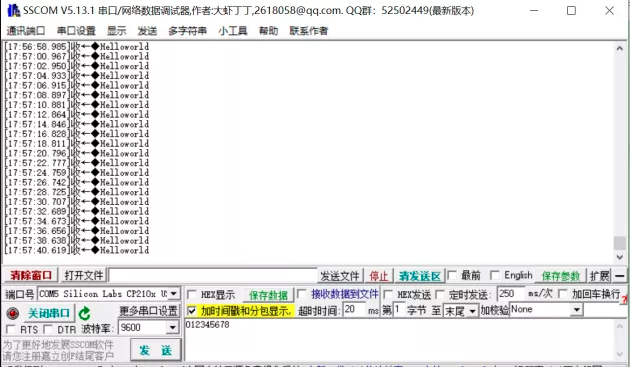
2) Receiving
information
Open
SSCOM, you can see that the USB controlled LoRa module can receive data, as shown
in the figure below:
Know
more about MYIR’s MYD-YA15XC-T development board from:
http://www.myirtech.com/list.asp?id=659
The MYD-YA15XC-T development board is using the MYC-YA15XC-T CPU Module as core controller board which is populated on a specially designed base board through 1.0 mm pitch 148-pin stamp-hole (Castellated-Hole) expansion interface. It is capable of running Linux OS. MYIR also offers MY-CAM011B Camera Module, MY-RGB2HDMI Module, MY-WF005S WiFi/BT Module, MY-WIREDCOM RPI Module (RS232/RS485/CAN) and MY-LCD70TP-C LCD Module as options for the board.
MYIR provides custom design services based on the MYD-YA15XC-T, whether reducing, adding or modifying the existing hardware according to customer’s requirement.
|