--- RGB-to-HDMI, DVP Camera, WiFi/BT, COM with Raspberry PI Compatible Pins
Flexible Design of the Development Board
The MYD-YA15XC-T development board is another design of MYIR based on STM32MP1 processor. Compared with the first product MYD-YA157C, the MYD-YA15XC-T has introduced a more open design concept to focus on the rapid verification of interface functionality, and can flexibly adapt to various modules, thus improving the efficiency of selection and verification in the early stage.
The MYD-YA15XC-T is composed of a core controller board MYC-YA15XC-T CPU Module and a base board. The MYC-YA15XC-T is populated on the base board through 1.0 mm pitch 148-pin Castellated-Hole expansion interface, and has integrated the STM32MP151 processor, PMIC, DDR3L and Flash. The MYD-YA15XC-T base board has extended many peripherals including Debug Serial port, USB Type-C DRP, Dual USB2.0 HOST, Gigabit Ethernet, Micro SD Card Slot, LCD, Camera, etc. It has also introduced pin header design to brought out a number of IOs to allow a variety of modules can be quickly integrated on this development board. For example, the 2 x 20-pin Raspberry PI interface design with 5 different IO configurations can realize various industrial applications.
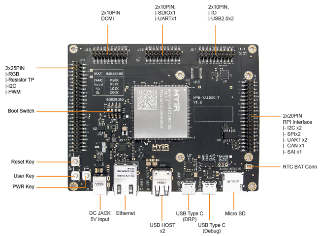
MYD-YA15XC-T Development Board Top-view
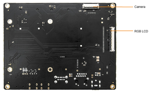
MYD-YA15XC-T Development Board Bottom-view
In below image, the MYD-YA15XC-T is connected with a RGB to HDMI module (MY-RGB2HDMI), a DVP camera module (MY-CAM011B), a WIFI/BT module (MY-WF005S), a COM RPI module (MY-WIREDCOM) and a 7-inch LCD module (MY-LCD70TP-C).
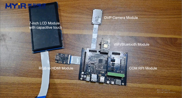
MYD-YA15XC-T Connects with Extension Modules
MYIR also incorporates a variety of third-party modules with the Raspberry PI interfaces, such as the 9-axis motion sensor ICM-20948 module, which has implemented the functions of 3-axis gyroscope, 3-axis accelerometer, 3-axis magnetometer and digital motion processor. Another example is the e-ink screen E-paper module, which has low power consumption, wide viewing Angle and can still be clearly displayed when power is off. As well, the SX1262 LoRa module has realized the functions of multi-level relay ultra-long-distance communication, low-power wake-up communication and encrypted transmission.
MYIR is also testing more modules from the third party. Please contact us for more information.
Application Test of MY-WIREDCOM RPI Module
The MY-WIREDCOM RPI module provided by MYIR has I2C, SPI, RS232, RS485 and CAN. More details can be visited from http://www.myirtech.com/list.asp?id=665.
Just note the MYD-YA15XC-T development board is using STM32MP151A by default. The 151 processor can not support CAN (only 153 and 157 can support). We will demonstrate the communication of RS232, RS485 and SPI via this module. And a 5V power adapter, a USB to UART module and a Type-C cable are required.
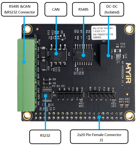
MY-WIREDCOM RPI Module
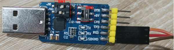
USB to UART module
|
Mode
|
SW1
|
SW2
|
|
USB (1)
|
RS485 (2)
|
|
USB to TTL
|
On
|
Off
|
Down (232-485)
|
|
USB to RS232
|
On
|
Off
|
Up (232-TTL)
|
|
USB to RS485
|
On
|
On
|
Down (232-485)
|
Settings of the USB to UART Module
1. Demonstration of RS232 data sending and receiving:
Wiring:
- Connect pin 1 and pin 2 on the back of the MY-WIREDCOM module to pin 1 and pin 2 on the J15 interface of the MYD-YA15XC-T development board, and the other pins are also seated by numbers.
- Set USB to RS232 mode for the USB to UART Module, connect the RS232 TX of the module to the RS232 RX of the MY-WIREDCOM module, the RS232 RX of the module to the RS232 TX of the MY-WIREDCOM module, GND to GND, and then connect it to the USB port of the computer.
- Connect the Type-C cable to the computer and the Debug interface of the development board. Connect the development board with 5V power supply and then enter the system.
In the root directory of the system, we have prepared the test program of the interface in advance, which can be obtained from the SDK provided by MYIR.
1) Open a serial port tool on the computer, select baud rate 115200, and connect the serial port.
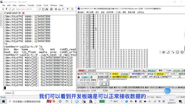
2) Receive data: Input a receiving instruction of RS232 from the development board, and then send data from the computer. We can see that the development board can receive data normally.
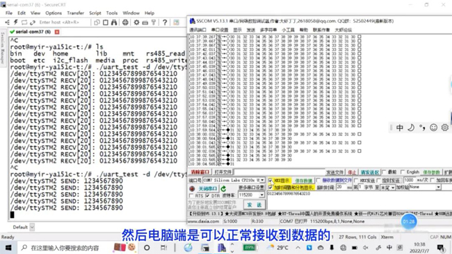
3) Send data: Then send data from the development board through RS232 port, and the computer can receive the data normally.
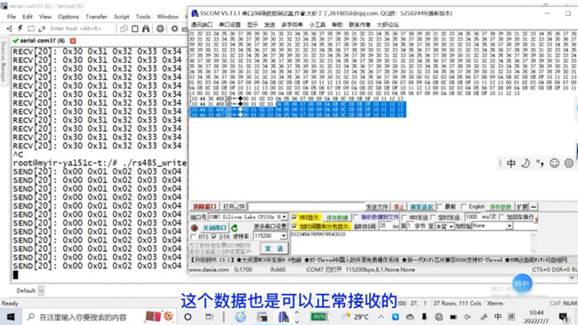
Demonstration of RS485 data sending and receiving:
Wiring:
- Set USB to RS485 mode for the USB to UART module, connect RS485 A of the module to RS485 A of the MY-WIREDCOM module, RS485 B of the module to the RS485 B of the MY-WIREDCOM, GND to GND, and then connect with the computer.
1) Set the baud rate to 115200 for the computer and connect to the serial port
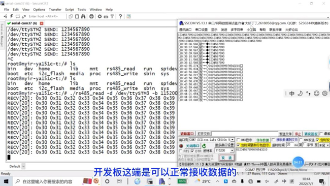
2) Receive data: Input a receiving instruction through the prepared test program onto the development board and send data from the computer. We can see that the development board can receive data normally.
3) Send data: Then send data from the development board, the computer can also receive data normally.
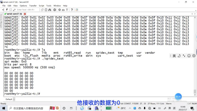
3. Demonstration of Receiving and Sending SPI data itself:
Run the prepared test program on the computer first. We can see that the received data is 0 when disconnected.
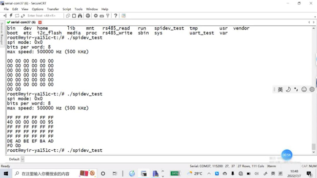
Wiring:
1) The H7 and F11 of the MY-WIREDCOM module can receive and send data spontaneously. Connect the MOSI and MISO ends of H7 and F11 with a cable.
2) Run the test program on the computer, and you can see that the data can be received.
We have also introduced above testing methods in the development documenations along with the MYD-YA15XC-T board. If you have any query during testing, you can also contact MYIR's support team: support@myirtech.com
|