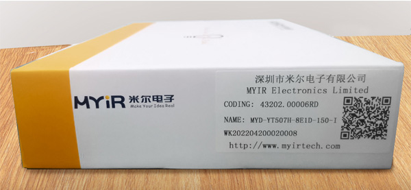
Hello everyone, today we are going to explore and experience MYIR’s high-performance industrial platform MYD-YT507H development board. The board has built around a CPU Module MYC-YT507H, combined with Allwinner’s T507-H Automotive Grade Processor. It is very attractive since its release due to the cost-effective Cortex-A53 SoM, pricing at only $30+. We can easily see the product model and production batch number on the label on the side of the packaging box after receiving the development board.
After opening the package, you will find the following items included:
|
Item
|
Describe
|
|
Board
|
1 x MYD-YT507H board (including MYC-YT507H CPU Module)
|
|
Cable
|
1 x USB Type-A to Type-C cable
|
|
Power adapter
|
1 x 12V/5A Power adapter
|
|
Power jack adapter
|
1 x DC power jack adapter
|
|
Quick Start Guide
|
1 x Quick Start Guide
|
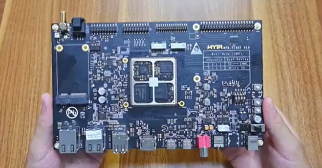
MYD-YT507H Development Board
We can find the label on the package shows this MYD-YT507H Development Board is 8E1D version (1GB LPDD4 and 8GB eMMC). It is populated with the MYC-YT507H CPU Module. Measuring only 43mm by 45mm, the module is integrated with the T507-H processor, LPDDR4, eMMC, EEPROM and PMIC. The T507-H processor has a 1.5GHz quad-core Cortex-A53 CPU and a Mali-G31 MP2 GPU so its image processing capabilities are powerful, and has multiple video inputs (MIPI CSI / parallel CSI) and outputs (RGB / 2 * LVDS / HDMI / CVBS out). The features are fully reflected on the development board. The processor can also support H.265 4K@60fps decoding, H.264 4K@25fps video encoding and most popular types of video and image decoding formats.
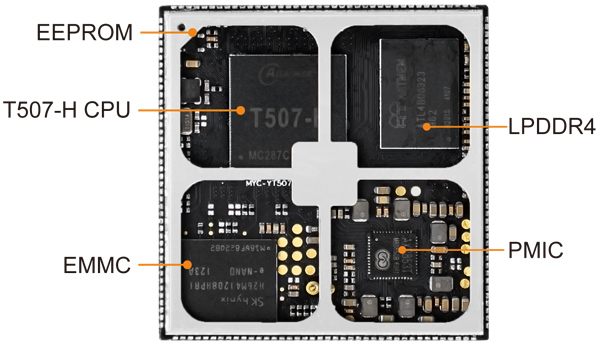
MYC-YT507H CPU Module
MYIR will burn the factory program image with relatively complete functions for the board. If the user wants to burn the Ubuntu system, he can get the develop resources from MYIR.
First, let’s see the peripheral interfaces on the top of the board.
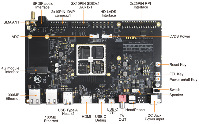
MYD-YT507H Development Board Top-view
Dual Ethernet Interfaces: One Gigabit Ethernet with YT8511H PHY and 10/100Mbps Ethernet with YT8512H PHY
USB: 2 x USB 2.0 Host with Type-A connectors;
HDMI: 1 x HDMI 2.0a;
Debug and USB C: Both use the Type-C connectors. The Debug port is used to communicate with the serial port of PC; The USB C port can connect to a USB disk or a mouse via one OTG transfer cable. The connected mouser can interact with PC screen to operate the system carried by the board.
CVBS: The first generation of audio and video output interface; It can be seen on many old-fashioned TVs.
Headphone: supports 3.5mm headphone output, it can also be used as audio out when connected to a speaker and a 5V USB power.
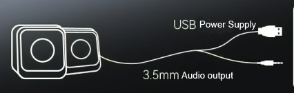
Speaker: Line out 8 Ω 5W small speaker output;
DC Power Jack: It can be connected to a 12V DC power supply and has a dial switch beside it for power on and off operations.
Reset Key: for Reset operation
FEL Key: When we connect USB C Debug port with PC directly, we can use a program provided by ALLWINNER through the FEL key to update the eMMC image.
Power On/Off Key: for Power On/Off operations
Boot Switch: select booting from the EMMC or SD card following MYIR’s documentations
RPI Interface: compatible with Raspberry PI standard 40-pin extension interface to carry out GPIO/TWI/UART, can be adapted to MYIR’s MY-WIREDCOM RPI module to extend RS485 and RS232 functions.
LVDS Interface: Dual link LVDS interface, can be adapted to MYIR’s MY-LVDS070C LCD Module with Capacitive Touch Screen
ADC: Supports 5-channel ADC input to convert analog signals to digital signals
2 x 10-pin Header: 1 x SDIO and 1 x UARTx1, can be adapted to MYIR's MY-WF005S WiFi/BT Module
DVP Camera Interface: supports FPC cable connection from the bottom of the board or IDC cable connection from the top of the board; can be adapted to MYIR’s MY-CAM011B Camera Module
SPDIF Audio interface: SPDIF optical output, which can convert optical fiber signals to audio signals through conversion modules;
SMA ANT: 4G module antenna interface;
4G Module interface: One USB based Mini-PCIe interface for 4G LTE module;
RTC Battery Interface: connect an external RTC battery when the MYD-YT507H development board is power off or in standby mode to ensure the accuracy of the internal clock.
Next, lets see the bottom design of the MYD-YT507H development board.
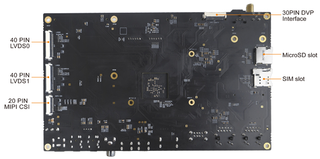
MYD-YT507H Development Board Bottom-view
LVDS0 and LVDS1: 2 x Single-channel LVDS Display interface which can be adapted to two 7-inch MY-LVDS070C LCD Modules
MIPI CSI Interface: 24-pin FPC connector, can be adapted to MYIR’s MY-CAM003M Camera Module
The two interfaces on the right are an SD card slot and a SIM card slot.
Let's start the power on demonstration.
Steps for connecting the development board:
1. Connect the Type-C data cable to the computer's USB port, and then connect the other end to the MYD-YT507H development board's USB C Debug interface.
2. Connect the MYD-YT507H development board to the DC power supply, and then turn the dial switch to boot from eMMC;
3. Select the appropriate terminal on the computer, select the baud rate of 115200, and then turn the power switch on. We will see the board is powered on.
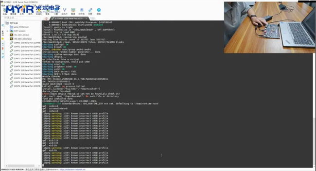
At this step, the kernel is started and the power on operation is completed after printing.
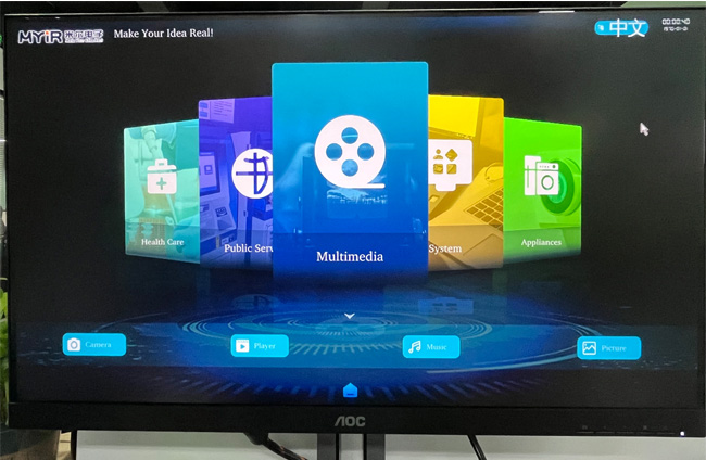
4. If you need to display, you can connect HDMI to the monitor to display MYIR’s customized desktop system, and connect the USB mouse to operate.
Video Demonstration:
https://youtu.be/vFXUIv0vVvc
|

