4. Development of applications (2)
4.7 The corresponding relationship
between ttymxc and uart
A: UART1 corresponds to ttymxc0
UART2 corresponds to ttymxc1
UART3 corresponds to ttymxc2
…
4.8 How to calculate GPIO numbers,
how to use the GPIO?
A: Make sure the GPIO in dts is not used before
using the GPIO. Define the GPIO in dts, generate new dtb, program it to the
board, then the board is able to input and output via the GPIO.
Calculation formula for GPIO number: (n-1)*32 +m
Examples:
LCD_DATA14 is gpio3.io19.
(M-1)*32+n = (3-1)*32+19=83
Set GPIO to output, set high/low voltage of GPIO:
echo 83 > /sys/class/gpio/export (Set the GPIO number)
echo out > /sys/class/gpio/gpio83/direction (Set GPIO to output)
cat /sys/class/gpio/gpio10/value (Check the high/low voltage of GPIO)
echo 0 > /sys/class/gpio/gpio10/value (Set high/low voltage of GPIO)
4.9 How to enable/disable the
Ethernet ports?
A:
The eth0 is brought out from MYC-Y6ULX CPU module directly. If only one
Ethernet port is needed, we may disable other Ethernet ports in dts. Meanwhile,
you need to move the configuration for mdio in dts to the ethernet port which you
want to use.
Two
RJ45 connectors on MYD-6ULX board: CN2 is eth0, CN1 is eth1.
Example
code for modifying one Ethernet port:
&fec1 {
pinctrl-names =
"default";
pinctrl-0 =
<&pinctrl_enet1>;
phy-mode =
"rmii";
phy-handle =
<ðphy0>;
phy-reset-gpios =
<&gpio5 9 GPIO_ACTIVE_LOW>;
phy-reset-duration
= <26>;
status =
"okay";
mdio {
#address-cells
= <1>;
#size-cells
= <0>;
ethphy0:
ethernet-phy@0 {
compatible
= "ethernet-phy-ieee802.3-c22";
smsc,disable-energy-detect;
reg =
<0>;
};
};
4.10 How to add other baud rate for
serial port?
A:
Add kernel source code in “/driver/tty/serial/serial_core.c”. Example code:
…
static const struct baud_rates baud_rates[] = {
{ 921600, B921600
},
{ 460800, B460800
},
{ 230400, B230400
},
{ 115200, B115200
},
{ 57600, B57600 },
{ 38400, B38400 },
{ 19200, B19200 },
{ 9600, B9600 },
{ 4800, B4800 },
{ 2400, B2400 },
{ 1200, B1200 },
{ 0, B38400 }
…
4.11 PWM control
program
A: We only provide the output configuration of
PWM below, this is not enough, you need to add PWM node according to the pin
you used by modifying dts.
echo 100000 > /sys/class/pwm/pwmchip0/pwm0/period
echo 50000 > /sys/class/pwm/pwmchip0/pwm0/duty_cycle
echo 0 > /sys/class/pwm/pwmchip1/export
echo 100000 > /sys/class/pwm/pwmchip1/pwm0/period
echo 50000 > /sys/class/pwm/pwmchip1/pwm0/duty_cycle
echo 0 > /sys/class/pwm/pwmchip2/export
echo 100000 > /sys/class/pwm/pwmchip2/pwm0/period
echo 50000 > /sys/class/pwm/pwmchip2/pwm0/duty_cycle
echo 0 > /sys/class/pwm/pwmchip3/export
echo 100000 > /sys/class/pwm/pwmchip3/pwm0/period
echo 50000 > /sys/class/pwm/pwmchip3/pwm0/duty_cycle
4.12 What are the LED1 & LED2 of
Ethernet port for?
A: LED1:
data transmission indicator (green). LED2: connection indicator (orange).
4.13 How to make MYD-6ULX support
LVDS?
A: Convert
RGB to LVDS. Below circuit designs are for your reference.
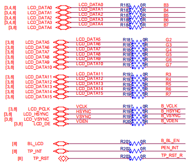
4-13-1
Example circuit 1
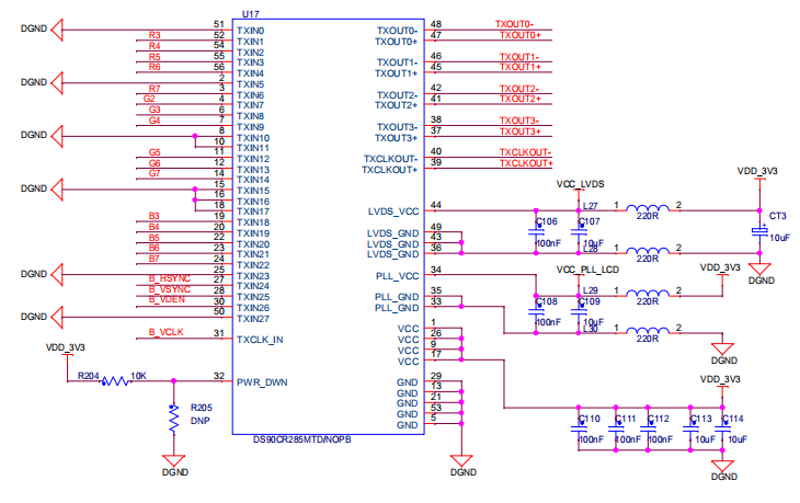
4-13-2
Example circuit 2
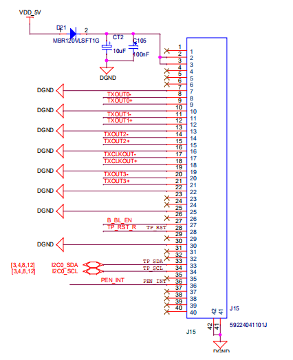
4-13-3
Example circuit 3
|


